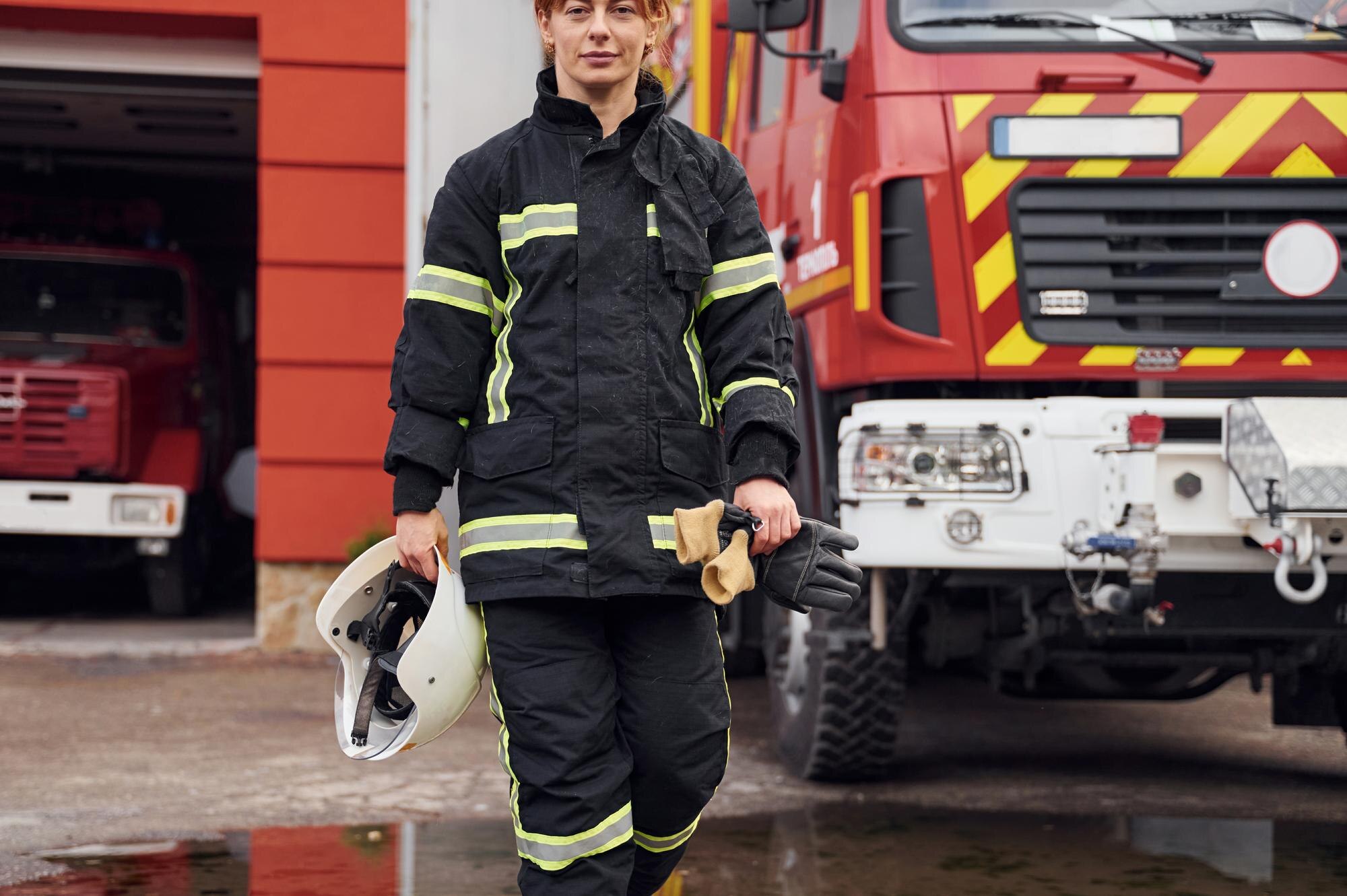
International Fire Code
Mandates in-building public-safety radio coverage of 95% general and 99% critical area for first responders.
Public Safety DAS / ERCES
Emergency Responder Communication Enhancement Systems (ERCES) designed, installed, and certified to IFC 510 and NFPA 1225. We hold a 100% AHJ first-pass approval rate across 150+ public safety DAS projects.
The problem
Modern construction materials such as low-E glass, concrete, and metal cladding kill up to 80% of public-safety radio signal. Without a code-compliant ERCES, first responders cannot communicate inside your building, and the fire marshal will not clear your Certificate of Occupancy.
Loading model…
| Material | Loss | Note |
|---|---|---|
| Low-E glass | 30 dB | per pane |
| Concrete floor | 15 dB | per level |
| Metal cladding | 40 dB | — |
| Parking garage | 50 dB | below grade |
| Elevator shaft | Total block | dead zone |
The difference
A failing benchmark test is the legal trigger for an ERCES. Toggle the building below to see how a roof donor antenna, a COMBA bi-directional amplifier, and a coax riser carry public-safety signal to every floor, the outcome we engineer and then prove with an on-site grid test.
Loading building…
| Floor | Riser gain | Before (dBm) | Before coverage | After (dBm) | After coverage |
|---|---|---|---|---|---|
| F7 | 10 dB → +9 dBm | -122 | 4% | -78 | 95% |
| F6 | 8 dB → +10 dBm | -118 | 8% | -74 | 96% |
| F5 | 8 dB → +10 dBm | -110 | 16% | -70 | 97% |
| F4 | 8 dB → +10 dBm | -104 | 27% | -67 | 99% |
| F3 | 5 dB → +13 dBm | -96 | 41% | -63 | 98% |
| F2 | 5 dB → +13 dBm | -88 | 58% | -60 | 99% |
| G | 5 dB → +18 dBm | -72 | 78% | -58 | 99% |
| Whole building | — | — | 33% · FAIL | — | 98% general, 99% critical · PASS |
Code minimum · ≥95% general / ≥99% critical @ ≥ -95 dBm · IFC 510 / NFPA 1225Illustrative, modeled on a real 7-floor project.
Architecture · Passive
A single bi-directional amplifier distributes public-safety signal over coaxial cable, the most cost-effective path to fire-code compliance. Play the signal flow to follow it from the roof donor antenna out to every floor antenna.
Loading schematic…
| Stage | Element | Feeds | Role |
|---|---|---|---|
| 1 | Donor antenna | BDA | Roof donor antenna, aimed at the public-safety simulcast site |
| 2 | BDA | S1–S5, annunciator | COMBA class A bi-directional amplifier, 700/800 MHz, the single active element in the system |
| 3 | Splitters S1–S5 | A1–A10, two each | Passive 2-way splitter, divides RF power to the floor run, no power required |
| 4 | Antennas A1–A10 | Floor coverage | Ceiling dome antenna, radiates and receives on the floor |
| — | Annunciator | FACP | Dry contact alarms to the fire alarm control panel: AC fail, battery, donor loss, amplifier fail |
Passive DAS · All-RF over coax · Single BDA · Dry contacts → FACPClick any node — or any step or component below — to inspect it. Illustrative topology; antenna count and run lengths are set by the RF design.
Architecture · Hybrid
A fiber-optic backbone feeds distributed remote units throughout the building, ideal for large, complex, or multi-building layouts. Play the signal flow to watch RF convert to light at the master and back to RF at every remote.
Loading schematic…
| Stage | Element | Medium | Feeds | Role |
|---|---|---|---|---|
| 1 | Donor antenna | Coax | Master BDA | Roof donor antenna, aimed at the public-safety simulcast site and feeding the master unit |
| 2 | Master BDA | Fiber (OS2) | RU1–RU4 | Master BDA, 700/800 MHz fiber master. Converts amplified RF to optical and drives every remote unit over single-mode fiber |
| 3 | Remote units RU1–RU4 | Coax | A1–A8, two each | Fiber remote unit. Converts the optical backbone back to RF and amplifies locally, so run loss no longer scales with distance |
| 4 | Antennas A1–A8 | — | Zone coverage | Ceiling dome antenna on a short coax leg from its remote unit |
| — | SNMP management | Ethernet | Network / FACP | SNMP v3 management: per-remote alarms, gain and status reported to the network and to the head-end web interface |
Hybrid DAS · Fiber backbone + coax · Master BDA + remotes · SNMP v3 + webHybrid DAS, fiber backbone to remote units. Click any node — or any step or component below — to inspect it. Illustrative topology; remote count and zone layout are set by the RF design.
Technical specifications
Two proven approaches. Different strengths. Same mission: reliable coverage where it matters.
| Specification | Passive DASSingle BDA over coax | Hybrid DASFiber backbone + remotes |
|---|---|---|
| Architecture | All-RF passive over coaxial cable | Fiber backbone + coax distribution |
| Best-fit size | Up to 250,000 sq ft | Up to 1,000,000 sq ft |
| Coverage target | 95% general / 99% critical | 95% general / 99% critical |
| Scalability | Add coax runs, splitters, antennas | Modular fiber expansion |
| Redundancy | Battery backup at BDA; redundant donor | Dual fiber paths; redundant power |
| Remote units | Up to 32 per hub | Up to 32 per hub |
| Management | Dry-contact alarms to FACP | SNMP v3 + web monitoring |
| Best for simplicity, speed, and budget-sensitive projects. | Best for large scale, flexibility, and future-ready designs. |
Code compliance
Miss any one and the system is rejected. We ensure 100% compliance before installation, which is how we keep a perfect AHJ approval rate.
Minimum −95 dBm signal strength in all general areas.
Stairwells, fire command center, pump rooms, exit corridors, elevator lobbies.
All signal boosters listed specifically for in-building public safety.
Cable routes protected by 2-hour rated enclosures or CI cable.
Standby power for 24 hours quiescent + 5 minutes talk time.
GFCI protected, on emergency power where available.
System trouble and antenna malfunction alarms to the fire panel.
Recertification by a qualified vendor every 12 months.
Mandates in-building public-safety radio coverage of 95% general and 99% critical area for first responders.
The 2022 standard for ERCES coverage, survivability, and monitoring, which replaces NFPA 1221.
The listing standard every public-safety signal booster and BDA must meet under IFC 2021.
Federal rules that keep the system from interfering with other licensed bands.
The process
RF grid testing and coverage mapping.
iBwave modeling and equipment specs.
Permit filing and plan review.
BDA install and antenna placement.
Grid testing and DAQ verification.
AHJ inspection and final approval.
Benchmark grid test
We divide your building into a measurement grid and test the existing public-safety signal floor by floor against the code standard of 95% coverage in general areas and 99% in critical areas.
A documented failing test is what legally triggers an ERCES, and it pinpoints exactly where signal dies so nothing is guessed.
You get: a baseline coverage map of your building's dead zones.
iBwave predictive modeling
Your building is modeled in iBwave and a system is engineered to hit code coverage with margin. We set the head-end location, antenna placement, and signal balancing across every floor and zone.
Predictive modeling means we know the design passes before a single component is installed.
You get: a sealed design package with predicted coverage heat-maps.
Permit & fire-marshal review
We file the permit set and coordinate the design up front with your local Authority Having Jurisdiction (the fire marshal).
Pre-approval coordination is how we keep a perfect first-pass approval record, with no surprises on inspection day.
You get: an approved, permitted plan ready to build.
Code-built & monitored
The system is installed to the approved design, in fire-rated pathways, with battery backup and fault monitoring tied to your fire alarm panel.
A clean, code-built installation is what survives both inspection and a real emergency.
You get: a fully installed, continuously monitored system.
Prove it passes
We repeat the same grid test on the finished system to prove 95% / 99% coverage, and verify backup power and monitoring.
Objective, documented proof the system meets code, in writing, before inspection.
You get: an AHJ-ready acceptance report with RSSI coverage maps.
Signed off & occupied
The AHJ inspects, signs off, and certifies the system, which clears the public-safety requirement on your Certificate of Occupancy.
This is the approval that lets you legally occupy and operate the building.
You get: certification plus an annual-test plan to stay compliant.
What you receive
Every project includes documented RSSI coverage maps and compliance paperwork your fire marshal can sign off on.
Code-required grid test summary, formatted for fire-marshal sign-off.
Investment
ERCES Ready bundles every phase from survey to AHJ sign-off into a single scoped quote. No per-stage invoices, no surprise change orders.
RF grid testing of existing conditions.
iBwave model and full equipment specification.
Professional installation and setup.
Grid testing and compliance verification.
AHJ inspection and final sign-off.
ERCES Ready is our complete turnkey compliance package, covering site survey, iBwave design, installation, AHJ certification, and a 1-year warranty. We provide a fixed-price quote after your site survey, with no hidden change orders.
Get your custom quoteRecent ERCES installations
A 15-story senior-living high-rise failing public-safety coverage at 51%, brought to full compliance in four days.
Read case studyRetail50+sites deliveredTurnkey ERCES for new and existing supercenters, grid testing, design, install, AHJ approval, commissioning.
Read case studyHotel / Hospitality1stpass AHJ approvalA 7-floor hotel that failed its public-safety benchmark test, brought to full code coverage and approved on the first inspection.
Read case studyQuestions
Get started
Tell us about your building and timeline. Our ERCES experts will assess your situation and recommend the most cost-effective path to compliance.